WCS (Wireless Control System) is a centralised solution for lightweight wireless access points. WCS uses SNMP to communicate with controllers. WCS runs on both Linux and Windows.
There are three versions of WCS:
WCS Base (informs which APs a device is associated with)
WCS Location (can track a device to within less than 10 meters)
WCS Location and 2700 series Wireless Location Appliance (tracking of devices in real-time)
Thursday 17 April 2008
WLAN Management - Ciscoworks WLSE
WLSE is part of the Ciscoworks network management suite for autonomous APs. It's features include:
Configuration: Supports 2500 APs, configurations can be changed on mass
Fault and policy monitoring
Reporting: email, print and export reports
Firmware: centralised firmware upgrades
Radio management: parameter generation, network status and reports
WLSE Administration: logs, security, back and restore, diagnostics, redundancy
Key benefits:
+Improved security - IDS, rogue AP detection etc.
+Simplified AP deployment
+RF visibility
+Dynamic RF Management
+Simplified operations
WLSE requires seperate authenication ACS server, WLSE cut down version includes AAA. WLSE Express is intended for small to medium businesses
WLSE has two modes of setup: Automatic - DHCP, manually using setup scripts and CLI
WLSE Configuration Templates: plug and play deployment, automatic AP configuration, automatic RF configuration, optimal RF configuration. IDS features include automatic shutdown of rogue APs, man in the middle attacks, security policy checks, sensor mode APs.
Wednesday 16 April 2008
WLAN Management - Introduction
There are five elements to Cisco Unified Wireless Networks:
Client Devices - Cisco Compatible Extensions program includes services such as wireless mobility, qos, network management and security
+ 7920 wireless phone, PDA.
Mobility Platform - LWAPs are automatically configured by controllers using LWAPP.
+ Lightweight AP's and bridges
Network Unification - Seamless integration into routing and switching, controllers are repsonsible for IPS and RF management
+ Wireless LAN controllers, 6500 WiSM, ISR and 3750 integration
World-class Network Management - enabling WLANs to be seamless with the rest of the network, making them scaleable and reliable via Wireless Control System (WCS)
+ Features for design, control and monitoring
Unified Advanced Services - Support new mobility applications, wireless VoIP, network admission control, self-defending network, and intrusion detection.
+ Cisco Wireless Location Appliance, WCS, Self-defending Networks, NAC, WiFi phones and RF firewalls
Autonomous Access Points
Configuration on each individual AP, each AP controls it's own RF and mobility functions. Ciscoworks Wireless LAN Solutions Engine can be used to centrally manage the APs. Wireless Domain Services (WDS) provides radio monitoring communication management between the APs and CiscoWorks WLSE.
Lightweight Access Points
Configuration, monitoring and security handled by a centralised WLAN controller. LWAPs depend on controller for control and data transmission. Remote Edge Access Point REAP doesn't require the controller. Cisco WCS can centralise configuration, monitoring and management. WLC can be redundant between WCS groups.

Tuesday 15 April 2008
802.1x, Encryption and Authentication - 802.11i and WPA2
WPA2
+ Support for 802.1x and PSK
+ Similar key distribution and renewal to WPA
+ Supports proactive key caching PKC
+ Supports IDS
IDS is able to detect locate and mitigate rogue devices, manage RF interference, detect snooping, managment frames and hijacking attacks, enforce security configuration policies, perform forensic analysis and compliance reporting.
WPA and WPA2 operate in personal and enterprise modes. Products supporting 802.1x and PSK are enterprise, products supporting PSK only are personal products.
Enterprise WPA= 802.1x/PSK, encryption using TKIP/MIC
Personal WPA2=PSK, encryption using AES-CCMP
Enterprise WPA2=802.1x/EAP encryption using AES-CCMP
Personal WPA=PSK, encryption using TKIP/MIC
802.1x, Encryption and Authentication - WPA, 802.11i and WPA2
WPA is a standards based solution to address vulnerabilities in WEP.
Main features:
Authenticated Key Management - authentication via IEEE 802.1x or PSK
Unicast or broadcast key management - after successful user authentication message integrity and encryption keys are derived, distributed validated and stored on the client and AP
Utilisation of TKIP and MIC - Temporal Key Integrity Protocol (TKIP) and Message Integrity Check (MIC) are elements of the WPA standard.
Initialisation Vector Space Expansion - Per-packet keying via IV hashing and key rotation. IV is expanded from WE 24bits to 48bits.
WPA/802.11i authentication process:
Client and AP exchange initial associated request (probe) and agree security capability. Client authenticated by 802.1x Radius server. When successfully authenticated the server and client will present the same master key (PKM) to the AP. Next a four-way key handshake between client and server takes place, finally a two-way handshake between client and AP takes place a group transient key (GTK) which includes MIC.
Issues of WPA:
- Reliant on RC4
- Hardware may not support WPA
- WPA susceptible to DOS, if two bad MICs occur the BSSID is shutdown for 1 minute
- Dictionary attacks can reveal PSK
802.1x, Encryption and Authentication - PEAP
Protected Extensible Authentication Protocol (PEAP), with PEAP only the server requires a certificate, installing a certificate on every client is not required. The RADIUS server must support self-issuing of certificates.
PHASE1 - server-side authentication is performed and an encrypted TLS tunnel is created.
PHASE2 - Client is authenticated using EAP-MSCHAPv2 or EAP-GTC, GTP can use generic databases to authenticate, such as LDAP/NDS, MSCHAP enables MS active directory single sign-on.
Client associates with the AP, only AES traffic is permitted by the AP until RADIUS server authenticates. PEAP goes through phase1/2, the client authenticates the server using the CA to verify the certificate. The client and server establish a secure tunnel, the client submits it's credentials to the server inside the tunnel. The RADIUS server sends a session key in a success packet, the RADIUS server and client negotiate a session encryption key (based on WEP or 802.11i
At the end of the session the client sends an EAPOL logoff packet to the AP, from this point only AES is accepted from the client.
802.1x, Encryption and Authentication - EAP-TLS
Extensible Authentication Protocol - Transport Layer Security (EAP-TLS), TLS the replacement for SSL protocol, using PKI.
Requirements of TLS
1. Client must have a certificate so the network can authenticate it
2. AAA server needs a certificate so the client can authenticate it
3. Certificate Authority (CA) must provide certificates to the client and server
+ Windows single sign-on
+ Supported on Windows platform
Wireless client connects to AP using open authentication, AP only permits AES from client until authenticated by AAA server. Client sends EAPOL start frame to server, AP returns request/identify to client. Client sends it's NAI address to the AP which forwards it to the AAA server, client/server perform mutual authentication using certificate exchange, RADIUS server sends session key in success packet.
RADIUS server and client negotiate session encryption, based on client using WEP or 802.11i. Keys then used for the session. EAPOL logoff packet send from client at end of session, AP returns to only accepting AES.
802.1x, Encryption and Authentication - EAP-FAST
Extensible Authentication Protocol - Flexible Authentication via Secure Tunnelling (EAP-FAST) developed by Cisco, submitted to IETF.
+ LEAP uses strong passwords, but LEAP-FAST supports single sign-on for Windows
+ Doesn't use certificates
+ Supported on Windows
+ Full support for 802.1x, AES, 802.11i and TKIP
+ Supports WPA/2 authenticated key management on Win2k/XP
+ Supports roaming and centralised key management CCKM using Wireless Domain Services
+ Supports password expiration/change
PHASE0 (provision PAC) - client dynamically provisioned a Protected Access Credential (PAC) via a secure tunnel
PHASE1 (establish secure tunnel) - Client and AAA server such as ACS authenticate each other and establish secure tunnel
PHASE2 (client authentication) - Client sends it's credentials to the radius server, the radius server authenticates and establishes a client authorisation policy.
A wireless client can only transmit EAP until authenticated by AAA, client sends EAP over LAN (EAPOL) start frame to the AP, the AP sends a request/identify to the client. The client sends it's network identifier NAI to the AP, which the AP sends to the radius server.
The client and server perform mutual authentication (phase 1/2) and the RADIUS server sends a session key to the AP in a success packet. The client/server then negotiate a session key, the client and AP use the key during the session. When the session completes an EAPOL logoff packet is sent to the AP.
Sunday 13 April 2008
802.1x, Encryption and Authentication - Cisco LEAP
Lightweight Extensible Authentication Protocol (LEAP), is an 802.1x authentication type.
+ supported by WiFi WPA/WPA2.
+ Strong mutual authentication between client and RADIUS server
+ Supported on all Cisco products
+ Fast secure roaming between Cisco or Cisco compatible clients at layer 2 and 3
+ Single login with existing userid/password from Microsoft AD
+ Supported on range of OS
Client OS include: MS 98/XP/CE, OS X 9.x/10.x, Linux, DOS
RADIUS servers include: Cisco ACS, Meetinghouse Aegis, Interlink Merit, Funk Odyssey server
Wireless devices include: Cisco WAP/LWAP, WLAN controllers, Cisco unified wireless phone 7920, wireless bridges/repeaters, many Cisco and Cisco compatible WLAN clients
Cisco LEAP process:
1. No traffic permitted except EAP until authenticated
2. AP request/identify message, or start message from client
3. Client responds with userid, which is sent by AP to RADIUS server
4. Radius server authenticates the client via AP
5. Client authenticates the RADIUS server via AP
6. Authentication uses challenge/response, response uses MD5, when authenticated a RADIUS success message is sent to each party.
7. The radius server sends a Pair-wise Master Key (PMK) to the AP, a four-way handshake takes place, then the client can transmit and receive data through a protected session.
802.1x, Encryption and Authentication - 802.1x and EAP
802.1x was originally designed for port based authentication on switches, but has been adapted to enable authentication of wireless clients/WAPs.
+ RADIUS protocol with server can be used to authenticate users, this includes Cisco ACS server
+ Authentication is mutual between the client (supplicant) and server
+ 802.1x can be used with multiple encryption methods such as EAS/WPA/TKIP/WEP
+ Without user intervention 802.1x provides dynamic keys after authentication
+ One time passwords can be used to encrypt plaintext passwords
+ 802.1x supports roaming
+ User management is centralised (better management)
802.1x, Encryption and Authentication - Evolution of Wireless Security
Fascinating Chapter... :(
WEP (Wired Equivalent Privacy) is a very basic form of wireless security, static key is configured, it's not difficult to capture enough packets to decipher the key. IV (Initial Vector) can be configured to change the key after each packet, but this is not secure either.
- Susceptible to dictionary attacks
- Client doesn't authenticate the AP
LEAP, renamed Cisco Wireless EAP was Cisco's first attempt to improve security on wireless networks, it utilised the following:
+ Server based authentication, utilising 802.1x, passwords/one-time tokens/PKI/machine IDs
+ Dynamic WEP keys (session keys), re-authenticating the user periodically, negotiating a new key (CKIP)
+ Mutual authentication between client and RADIUS server
+ Cisco Message Intergrity Check (CMIC) - detects WEP attacks and replays
WPA - Wifi Alliance Group created interim security method prior to development of 802.11i. WPA utilises the following:
+ Pre-shared Key (PSK), or 802.1x user authentication
+ TKIP (Temporal Key Integrity Protocol, used to create per packet keying, and MIC (message integrity check).
+ Only software upgrade required
WPA2 - utilises AES for encryption and use of IDS to identify and protect from attacks, WPA2 generally requires a hardware upgrade.
Monday 7 April 2008
Wireless LAN QoS - Introduction
Wireless LANs operate in the same mannor as wired LANS at OSI layer 3 and above.
Where wired LANs implement CSMA/CD, wireless LANs (802.11) are not able to detect collisions, so implement collision avoidance - CSMA/CA. Collision Avoidance uses RF carrier sense, random back-off, inter-frame spacing.
802.1e is an approved standard for implementing QoS on wireless networks. Prior to 802.1e being standardised, Wifi Multimedia WMM created a QoS policy based on 4 queues, to prioritise traffic.
WLAN data from a client is sent between the LWAP and controller using LWAPP (Light Weight Access Point Protocol). A LWAP running LWAPP layer 2 will need to be in the same broadcast domain and IP subnet as the controller, however a LWAP in layer 3 mode doesn't have to be in the same IP subnet or broadcast domain. In layer 2 mode the LWAPP protocol is an Ethernet frame, but in layer 3 mode it is a UDP packet.
The following shows the process of QoS continuity is as follows:
1. WLAN controller frame packet marked with 802.q (CoS)
2. WLAN controller encapsulates frame with LWAPP, copies inner DSCP fields to outer LWAPP DSCP field, then maps the DSCP field to the outer CoS field using a mapping table.
3. LWAP forwards the IP packet to the client, it uses the 802.11e layer 2 QoS marking
Auto QoS
Automated tool for deploying QoS
+Simplifies QoS configuration
+Less chance of configuration error
+Makes deployment simpler, faster and cheaper
+Follows DIVSERV model
Phase 1 - AutoQoS VoIP: designed purely for VoIP, only one command required, supported on majority of switch/router platforms
Pahse 2 - AutoQos Enterprise: Extends to cover VoIP/video/data, only supported on routers
NBAR used for protocol discovery.
Prerequisites:
1. No existing QoS policies on interface
2. CEF enabled on interface
3. Correct bandwidth specified
Enable autoqos enterprise on a router interface: 'auto qos discovery', then 'auto qos'
Enable autoqos voip on switch interface: 'auto qos voip trust' for uplinks (trust markings), 'auto qos voip cisco-phone' (extends trust boundary to phone).
Verify AutoQos on routers:
- show auto discovery qos - auto discovery results
- show auto qos - view templates and initial configuration
- show policy-map interface - shows interface QoS statistics
Verify AutoQoS VoIP on switches:
- show mls qos maps - examine cos to DSCP mappings
Common AutoQoS problems:
1. Too many classes generated - manually consolidate classes
2. QoS configuration doesn't adapt to changing network conditions - re-run discovery
3. QoS configuration doesn't fit specific circumstances - manually configure QoS elements
End-to-end QoS - Control Plane Policing (CoPP)
Packets destined for the control-plane generally include routing protocol control packets, SNMP management traffic, packets destined for the local router's IP address, for example telnet.
It is important to configure QoS for the control-plane in order to prevent DoS attacks that could damage the network infrastructure, for example:
- High CPU utilisation
- Loss of routing updates and keep-alives, resulting in routing-flaps
- Slow response times including access through CLI and VTY lines
- Queue build-ups resulting in packet drops
MQC can be used to define 'trusted' traffic that is allowed un-restricted access to the control-plane, whilst policing all other traffic. QoS policies can be applied to the control-plane in the similar fashion as a router interface.
End-to-End QoS - Pre-classify
Pre-classify was designed to classify packets on the output of an interface before data is encrypted and tunnelled. In modern times service providers and customers want to classify traffic within VPN tunnels, providing SLA's to voice/video etc.
VPN aims to provide confidentiality, Authentication and data integrity.
When a packet enters a VPN it's original headers are encapsulated, this means that any QoS on the original headers will not be visible to the QoS mechanisms on the egress interface.
Good news is the old ToS field value is copied to the new headers, however if there is a requirement to classify based on source/destination address, for example, then the 'pre-classify' command need to be used. Pre-classify should be configured on the endpoint prior to the traffic entering the VPN tunnel.
Two common tunneling protocols are IPSEC and GRE, GRE has the advantage of being able to tunnel multicast/broadcast and routing protocol traffic, GRE is not able to provide confidentialilty using encryption.
IPSEC is a more secure protocol, which is able to encrpt only unicast traffic. IPSEC uses two mechanisms to protect data:
Authentication Header (AH) protocol 51: Operates in tunnel mode (adds headers) or transport mode (encapsulates entire packet). Ensures integrity and euthentication of packets.
Encapsulating Security Payload (ESP) protocol 50: Operates in tunnel mode (encrypts only the IP payload), transport mode encrypts the entire original packet.
The pre-classify command takes a duplicate of the original packet to that the service policy is able to examine the packet. This is only required where fields other than TpS need to be inspected (ToS fields are automatically copied from the original packet to the encrypted packet).
Pre-classify can only be configured on tunnel interfaces/virtual templates/crypto-maps.
"Where Do I Apply the Service Policy?
You can apply a service policy to either the tunnel interface or to the underlying physical interface. The decision of where to apply the policy depends on the QoS objectives. It also depends on which header you need to use for classification.
-
Apply the policy to the tunnel interface without qos-preclassify when you want to classify packets based on the pre-tunnel header.
-
Apply the policy to the physical interface without qos-preclassify when you want to classify packets based on the post-tunnel header. In addition, apply the policy to the physical interface when you want to shape or police all traffic belonging to a tunnel, and the physical interface supports several tunnels.
-
Apply the policy to a physical interface and enable qos-preclassify when you want to classify packets based on the pre-tunnel header."
Sunday 6 April 2008
Congestion Avoidance - Fragmentation & Interleaving
Provided that the software queue is empty packets go straight to the hardware queue, the hardware queue operates a FIFO policy, the implication of this is that delay sensitive voice packets may be queued behind large packets.
If a typical 1500 byte frame has a be sent on a 256000bits/sec link (256Kb) then a delay of 47ms is created (1500*8/256000).
To reduce the delay created by large queued data units fragmentation and interleaving can be enabled.
If a typical 1500 byte frame has a be sent on a 256000bits/sec link (256Kb) then a delay of 47ms is created (1500*8/256000).
To reduce the delay created by large queued data units fragmentation and interleaving can be enabled.
Congestion Avoidance - Payload & Header Compression
Layer 2 payload compression as the name suggests, compresses frames at layer 2. Payload compression is done on a link by link basis, on protocols such as HDLC/frame-relay/PPP/X.25/LAPB.
The following compression methods are supported on Cisco IOS:
-Stacker
-Predictor
-MPPC (Microsoft Point to Point Compression
Compression does induce an amount of delay, perference is towards hardware based compression, as software/hardware assisted requires more CPU cycles. Layer2 compression of payloads leaves the headers intact as they are required, layer 2 header compression will compress the headers, but leave the payload intact.
Layer 2 header compression sends the first packet in a flow with it's headers, then for all remaining packets in the flow, a hash is calculated and the headers are removed. The receiving router will determine which flow the packet is part of by reviewing the hash value.
Congestion Avoidance - Traffic Policing/Shaping Overview
Traffic Policing aims to limit the traffic rate to less than the physical rate of the interface, limit the traffic rate for particular classes and re-mark traffic.
Traffic Shaping aims to slow down the traffic rate to a value less than the physical rate, often to comply with SLA's. It is also able to shape traffic of different classes to different bit-rates.
- Shaping and policing both measure the traffic rate (sometimes within classes)
- Policing can be applied out and inbound, whereas shaping can only be done outbound.
- Shaping buffers excess packets (requiring extra memory), policing drops or re-marks traffic.
- Only policing can re-mark traffic
- Only traffic shaping can respond to network conditions and signals.
Saturday 5 April 2008
Congestion Avoidance - CBWRED
Class-based Weighted Random Early Detection (CBWRED) is a development on WRED which allows profiling of traffic based on class-maps, rather than enabling it at an interface level.
An example configuration of CBWRED:
!
interface FastEthernet 0/0
service-policy output enterprise_policy
!
class-map voice
match ip dscp ef
!
class-map bulk-data
match ip dscp af11
!
policy-map enterprise_policy
class voice
priority 128
class bulk-data
bandwidth 128
random-detect
random-detect dscp af11 22 55 10
class class-default
fair-queue
random-detect
!
show policy-map interface fa0/0 - verify configuration
Congestion Avoidance - WRED
Weighted Random Early Detection (WRED) works on the same principle as RED, but has the added flexibility of being able to distinguish between high and low priority traffic, identified by DSCP/IPP. This enables WRED to drop more packets of a lower priority to ensure high priority traffic is not affected.
The following shows the configuration required to enable WRED:
interface Hssi0/0/0
description 45Mbps to R1
ip address 10.200.14.250 255.255.255.252
random-detect
random-detect precedence 0 32 256 100
random-detect precedence 1 64 256 100
random-detect precedence 2 96 256 100
random-detect precedence 3 120 256 100
Wednesday 2 April 2008
Congestion Avoidance - Random Early Detection
Random Early Detection (RED) is a mechanism used to prevent tail-drop.
RED drops packets at random before a queue is full, the rate of drops increases as the queue grows. RED is not flow orientated and will drop packets at random without preference. Statistically packets in more aggressive flows will be dropped more frequently.
RED is only effective when the majority of traffic is TCP flows. Because non-TCP flows do not use window sizes they will not benefit from RED.
Three parameters are used to configure RED: low threshold, high threshold and Mark Probability Denominator (MPD). RED will drop one packet of MPD value, for example if MPD was 40, 1 in 40 packets would be dropped.
If the minimum threshold is too low then packets may be dropped too soon, when not necessary. If the maximum threshold is too high when RED will not be able to prevent global syncronisation.
Congestion Avoidance - Tail Drop Limitations
Tail drop occurs when a software queue is unable to hold any more packets arriving. The aim of congestion avoidance is to avoid tail-drop.
Effects of tail-drops include TCP global syncronisation, and TCP starvation
TCP Global Syncronisation occurs when packets from multiple TCP connections are dropped causing the TCP sessions to reduce their window size, once the queue is uncongested the window size is increased again causing tail-drop. Due to the fluctuating window size, and that it affects all TCP sessions it doesn't provide for effective performance.
TCP Starvation occurs then UDP traffic (unaffected by window size fluctuation) fills the queues and prevents TCP packets from entering the queue.
Random Early Detection (RED) is a solution to improve TCP performance
Sunday 30 March 2008
Congestion Management and Queuing - LLQ
LLQ (Low Latency Queuing) - offers all of the benefits of CBWFQ, but with the ability to offer low delay and jitter queues for supporing VoIP/ToIP. As with CBWFQ all traffic not identified using class-maps is assigned to the default-class, which uses all remaining available bandwith. Default-class can use FIFO or WFQ, also with WRED.
Strict priority queues enable low-delay transmission of real-time data, the queue is policed, this prevents starvation of the other queues.
Configuration of LLQ follows the same methods as CBFWQ, an additional 'priority' command is used to specify strict-priority queues.
E.g.
policy-map enterprise_qos
class voice
priority 50
class business
bandwith 200
class class-default
fair-queue
The policy above offers strict-priority queue for voice class, with bandwidth guarantee of 50Kb/sec, business class is guaranteed 200Kb/sec using CBWFQ.
Congestion Management and Queuing - CBWFQ
CBWFQ (Class Based Weighted Fair Queuing) - User-defined classes, each class is assigned it's own queue. Each queue can be configured with it's own (minimum) bandwith guarantee. Flexible class-maps are used to match traffic (flows) to queues.
CBWFQ can create up to 64 queues, with one for each user-defined class, each queue uses FIFO, with defined bandwidth guarantee and maximum packet limit, tail drop occurs if the maximum packet limit is reached. To avoid tail-drops WRED can be applied to specific queues.
A default-class is always present in CBWFQ which is used to queue any traffic not matching the user-defined queues. It is possible to define a minimum bandwidth guarantee for the default-class, otherwise it will use any remaining bandwidth available.
CBWFQ is not able to offer a queue suitable for applications that require low latency queuing.
Steps for configuring CBWFQ:
1. Define class-maps (match features described previously)
2. Create a policy-map, define parameters such as guaranteed bandwith/packet queue/queuing method
3. Apply policy-map to an interface in a specified direction
E.g. Guarantee minimum 120Kb/sec bandwidth for web-based applications, with a maximum queue limit of 90 packets, guarantee 20Kb/sec bandwidth for traffic from host 192.168.2.3, and fair-queue all other traffic
access-list 100 permit ip host 192.168.2.3 any
!
class-map web_application
match protocol www
!
class-map host_192.168.2.3
match access-group 100
!
policy-map enterprise_policy
class web_application
bandwith 120
queue-limit 90
class host_192.168.2.3
bandwith 20
class class-default
fair-queue
!
interface FastEthernet 0/0
service-policy output enterprise_policy
Congestion Management and Queuing - WFQ
WFQ (Weighted Fair Queuing) - Default queuing mechanism on serial interfaces less than E1 speed, it is used by modern queuing methods CBWFQ and LLQ. WFQ is a flow based queuing method, flows are assigned to FIFO queues.
Flows are identified by the following features:
-Src/Dst IP address
-Protocol number
-ToS
-Src/Dst TCP/UDP port number
When recieving a packet it's hash value is calculated, all packets in a flow will have the same hash value. The hash is calculated on the fields above. After the packet has had it's hash calculated if it is a new flow it is assigned a new queue, if it is part of an existing flow it is assigned to the same queue as the rest of the packets.
If a queue size is larger than congestive disgard threshold then it may be dropped. The priority of a packet or flow will influence the sequencing number. Higher priority packets are assigned a smaller sequence number so will be given preferential treatment. If all flows have the same priority interface bandwith is devided equally.
The number of queues is equal to the number of active flows, by default this is a maximum of 256 queues. When flows exceed the maximum configured value they are added to existing queues.

WFQ has a hold policy that covers every queue, when the hold threshold is exceeded any new packets are dropped, this is called 'aggressive dropping'. Aggressive dropping does have one exception, if the destination queue is empty then the packet will be accepted.
Every queue has a Congestion Discard Threshold (CDT), if the hold queue is not full but the CDT is reached then the packet will be dropped. This is called 'early dropping', the only exception is if a packet has a higher sequence number then that will be dropped instead.
WFQ is enabled using 'fair-queue' command on interface, 'fair-queue cdt_value' can be used to configure CDT. 'hold-queue max_limit out' can be used to set the hold queue limit.
Flows are identified by the following features:
-Src/Dst IP address
-Protocol number
-ToS
-Src/Dst TCP/UDP port number
When recieving a packet it's hash value is calculated, all packets in a flow will have the same hash value. The hash is calculated on the fields above. After the packet has had it's hash calculated if it is a new flow it is assigned a new queue, if it is part of an existing flow it is assigned to the same queue as the rest of the packets.
If a queue size is larger than congestive disgard threshold then it may be dropped. The priority of a packet or flow will influence the sequencing number. Higher priority packets are assigned a smaller sequence number so will be given preferential treatment. If all flows have the same priority interface bandwith is devided equally.
The number of queues is equal to the number of active flows, by default this is a maximum of 256 queues. When flows exceed the maximum configured value they are added to existing queues.
WFQ has a hold policy that covers every queue, when the hold threshold is exceeded any new packets are dropped, this is called 'aggressive dropping'. Aggressive dropping does have one exception, if the destination queue is empty then the packet will be accepted.
Every queue has a Congestion Discard Threshold (CDT), if the hold queue is not full but the CDT is reached then the packet will be dropped. This is called 'early dropping', the only exception is if a packet has a higher sequence number then that will be dropped instead.
WFQ is enabled using 'fair-queue' command on interface, 'fair-queue cdt_value' can be used to configure CDT. 'hold-queue max_limit out' can be used to set the hold queue limit.
Congestion Management and Queuing - RR & WRR
RR (Round Robin) - RR uses multiple queues, the packet schedular takes one packet from each queue and starts from the top again. If there is a large packet in one queue then there is a possibility that other queues may suffer temporarily.
All queues are of equal priority and it is not possible to prioritise traffic.
WRR (Weighted Round Robin) - modified version of RR, where specific weights can be added to queues. Custom Queuing (CQ) is a form of WRR where you can specify the number of bytes to be processed before moving to the next queue.
Congestion Management and Queuing - Priority Queuing
PQ - Priority Queuing uses four queues, high/medium/low/normal. Packets must be assigned to each queue, if packets are not assigned they will be put into the normal queue. Access-lists are commonly used to identify the traffic to be queued.
1. If packets exist in the high priority queue then packets in other queues will not be processed until it is empty.
2. If the high priority queue is empy then one packet will be processed from the medium priority queue.
3. If the medium priority queue is empty then a packet from the normal queue is processed.
4. If the normal priority queue is empy then a packet from the low priority queue is processed.
After processing one packet the packet schedular will always start from the beginning again, checking the priority queues in the order described above. The problem with this is that low priority queues may be starved if higher priority queues have traffic waiting constantly.
Cisco IOS command priority-list can be used to define the queue that packets should be sent to.
Congestion Management and Queuing - FIFO
First in First Out (FIFO) FIFO uses a single queue, and requires no configuration effort. Packet class/priority/type are not considered when queued. Real-time applications may be queued behind bulk data, and also dropped if necessary.
On high bandwidth interfaces FIFO is considered an appropriate queuing mechanism.

On high bandwidth interfaces FIFO is considered an appropriate queuing mechanism.
Congestion Management and Queuing - Intro
Queuing is a technique that deals with temporary congestion, for long term congested links recommended practise is to upgrade the link.
Default queuing mechanism on all interfaces, except those less than 2048Kb/sec is FIFO - first in first out.
Software queues are only used when the hardware queue is full (transmit queue TxQ), hardware queue quickly transmits packets in the order they are recieved.
Default queuing mechanism on all interfaces, except those less than 2048Kb/sec is FIFO - first in first out.
Software queues are only used when the hardware queue is full (transmit queue TxQ), hardware queue quickly transmits packets in the order they are recieved.
Friday 28 March 2008
Network Based Application Recognition - NBAR
NBAR is capable of detecting applications/flows through a router. It is limited in the applications that it can recognise, PDLM's can be added to NBAR allowing recognition of additional applications. NBAR is simpler than access-lists and also supports HTTP MIME types, and stateful connections.
NBAR can be integrated into QoS to identify traffic and classify, using protocol-discovery.
ip nbar pdlm name_of_pdlm - Add a new PDLM located in flash
ip nbar port-map name_of_protocol tcp/udp port_number - map protocol to port
ip nbar protocol-discovery - enable NBAR protocol discovery on an interface
match protocol protocol_name - identify traffic in class-map using NBAR.
http://www.cisco.com/pcgi-bin/tablebuild.pl/pdlm - Download PDLMs
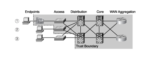
QoS - Trust Boundaries
As we all know, we should perform traffic classification and marking as close to the network edge as possible (this means the access layer switches, or even devices connected to the access-layer).
Defining a trust boundary is important, it prevents unauthorised software/devices from marking packets with a priority that could be detrimental to other critical traffic flows.
There are three main trust boundaries at the access layer; host/IP phone/switch, this would generally be CoS markings, if you wish to mark at layer 3 (DSCP) then a distribution switch may be your trust boundary, as illustrated below.
Thursday 27 March 2008
Diffserv model - IPP and DSCP
ToS field can be used for IP precedence, or DSCP (8 bytes)
IP Precedence is old, only uses 3 bits to define priority, 8 possible values, only 6 user-definable.
DSCP is new, backwards compatible with IPP, uses 6-bits
Default Per-hop-behaviour (PHB) is '000' for three most significant bits, queuing is best-effort service.
Assured Forwarding (AF) -three most significant bits, guaranteed bandwidth
Expidited Forwarding (EF) - three most significant bits, provides low delay service
Expidited Forwarding - Ensures low delay, low jitter, designed for real-time applications. It is important to limit the bandwidth of EF so that it doesn't starve other classes, ideally EF is used with admission control. During congestion EF polices bandwidth.
Non DSCP complient voice applications mark IPP as 101 (5-critical), the most significant bits of EF are 101, so enables backwards compatability.
Assured Forwarding - AF provides four queues for four classes of traffic (AF1x/AF2x/AF3x/AF4x), the 'x' value defines drop probability. There is no priority among the queues.
AF11 is less likely to be dropped than AF13. There are 3 drop priorities, low1, medium2, high3.
Each AF class is backwards compatible with IPP values, e.g. AF21 is equal to IPP2
EF class is backwards compatible with IPP value 5 (binary 101).
When implementing QoS it is important to ensure that enough bandwidth is reserved for each queue to avoid delay or drops. Providing an AF queue is not policed, it can consume more bandwidth providing it is available.
Classification & Marking - @layer 2 MPLS
Packets entering an MPLS network have an additional 4-byte header added, this header contains the parameters for MPLS.
Within the MPLS header there is a field called EXP, this experimental field is used for marking priority. 3-bits are available for specifying priority, just like CoS field in 802.q frames, or IP precedence.
On the edge of the MPLS network, when an IP packet arrives the three most significant bits of the ToS (layer 3 QoS marking) are copied to the EXP field of the MPLS header. The three bits are called IP precedence.
It is possible for the MPLS service provider to chose not to copy the IP precendence to the EXP field, and instead configure the EXP field themselves, this leaves the ToS field available for the customer to mark as appropriate.
Classification & Marking - @layer2 Frame-relay/ATM
QoS marking at frame-relay and ATM isn't very sophisticated, in frame-relay the DE 'discard elligable' bit is set to 1 if it is allowed to be dropped.
ATM uses the same principle, with a field called CLP, when set to 1 the cell is a good candidate for dropping.
ATM uses the same principle, with a field called CLP, when set to 1 the cell is a good candidate for dropping.
Classification & Marking - @Layer 2 Ethernet
CoS - Class of Service is a method of marking packets at layer2, commonly done by an access switch, or IP phone.
802.1q VLAN trunking protocol is a 4-byte header field (VLAN ID) added to an Ethernet frame. Within the VLAN ID field is a 3-bit field called 'user priority' this is called 802.1p
The 802.1p field allows up to 8 different values that can identify different priorities of traffic.
The image below shows the placement of 802.1q VLAN ID field, and 801.p within it.
Classification & Marking
Classification and marking is the process of identifying, then grouping traffic. Traffic descriptors are methods of identifying traffic to be put into classes, the following are methods of traffic identification:-
Ingress (incoming interface)
Source/destination IP address
CoS (class of service) layer 2 marking on ISL/802.1p frame
IP Precedence/DSCP layer 3 marking on IP packet
MPLS EXP value on MPLS header
Application type
Common practise nowadays is to mark the packet using deep-inspection as close to the edge as possible, then as the packet traverses the network only the packet marking needs to be checked.
Wednesday 26 March 2008
QoS - Models
Best Effort - no configuration required, no differentiated service to applications
Integrated Services (intserv) - Signals to reservice service and guarantee quality, uses RSVP signalling protocol. Model also known as hard-qos, signalling is on a per flow basis, so can become bandwidth intensive.
Differentiated Services (diffserv) - most modern, uses traffic classification and marking on a per router basis.
QoS - Methods of Configuration
There are mutliple methods to configure QoS, the best tool to use depends on what you want to achieve, and your familiarity with router configuration.
1. Legacy command-line interface (CLI) - old, complicated, prone to errors in configuration
2. Modular QoS Command Line (MQC) - new, efficient, uniform across all router platforms
-define traffic classes - class-map
-define treatment to traffic classes - policy-map
-apply QoS policy to an interface in a direction - service-policy in/out
3. AutoQos - Automatic QoS policy configuration, including traffic identification, marking, queuing
4. SDM QoS Wizard - Graphical web interface, QoS configuration by software wizard
Recommended method of QoS configuration is MQC.
QoS - Major Issues
QoS isn't just for fun, it aims to resolve the following key issues experienced in enterprise networks:
Available bandwidth: Obviously traffic flow is limited by the link with least bandwidth (bottleneck). Available bandwidth = total bandwidth/number of flows. Methods to fix lack of bandwidth include: upgrade links (costly), classify and mark traffic and use queuing techniques. Another solution is to use compression such as cRTP, this can be CPU intensive.
End to end delay: Four types of delay-
1. Processing delay -time taken for device to move packet from ingress to egress interface
2. Queuing delay - time spent in queue before serialisation
3. Serialisation delay - time taken to send all bits onto medium
4. Propagation delay - time taken to traverse medium
Variation of delay (jitter): Packets within a flow arrive out of order, and end to end delay may vary. Real-time applications like video and voice require packets to arrive in the order that they were sent. To resolve the problem a de-jitter buffer is used on the router, it (where delay is minimal) re-orders packets before passing them to the application.
Packet loss: Packet loss occurs due to router buffers filling up, and packets get dropped. Routers may drop some packets in order to make room for higher priority traffic. UDP traffic is connectionless, without the flow control of TCP, this means that packets have to be resent, which is costly for VoIP and video applications.
VoIP- Odds and ends
Important stuff....but already memorised
cRTP - RTP header compression - beneficial on links less than 2mb/sec,
VAD - Voice Activated Detection - Substantial bandwidth savings, theory is that conversations involve substantial amounts of time where no voice is spoken, with VAD enabled there durations are not packetised. Another premise is that when one party is talking, the other is not, so there is no need to packetise voice in that direction.
Fragmentation - VoIP packets are typically small, so when a small VoIP packet is in an outbound queue behind a large data packet it has an impact on the quality of the call. Fragmentation reduces the maximum transmission unit (MTU) so that the VoIP packets are not delayed waiting for large packets to leave the output queue.
VoIP - Pulse Code Modulation
PCM - Pulse Code Modulation:
PCM is a method of converting analogue voice signals to digital voice signals... this is how it works!...
8000 samples of voice are collected and recorded every second, each sample is quanitizised by assigning an 8bit binary number based on voltage/height, this produces a bit rate of 640000 bit/sec (64Kb/sec).
PCM is un-compressed, and can be transmitted nicely within a channel of an E1 trunk! Easy
VoIP - Analogue to Digital Conversion
In order to convert analogue electrical signals into digital binary numbers the following steps take place:
1. Sampling - Period capturing and recording of voice (resulting in a PAM Pulse Amplitute Modulation signal)
2. Quantization - Assigning numeric values to the voltage (or height) of each sample
3. Encoding - Representing the numeric values in a binary format
4. Compression (optional) - Aims to reduce the number of bits transmited to conserve bandwidth.
High quality voice calls have a high sampling rate, the down side to this is that generates a higher bit-rate, which is more bandwidth intensive!
VoIP - Interfaces
Interfaces!...
Digital interfaces: (multiple channels)
ISDN - PRI [e1/t1]
ISDN - BRI
Analogue interfaces: (single channel)
FXS (phone/fax/modem ~ringing)
FXO (PSTN CO switch ~battery, dial-tone, digit collection)
E&M (trunk PBX-PBX connectivity)
Digital interfaces: (multiple channels)
ISDN - PRI [e1/t1]
ISDN - BRI
Analogue interfaces: (single channel)
FXS (phone/fax/modem ~ringing)
FXO (PSTN CO switch ~battery, dial-tone, digit collection)
E&M (trunk PBX-PBX connectivity)
Introduction
I will be writing this blog, whilst studying for the Cisco Optimising Converged Cisco Networks (ONT).
The aim is to capture the key information from my studying for the examination...
The aim is to capture the key information from my studying for the examination...
Subscribe to:
Posts (Atom)
.jpg)